
Tactile Campus Map
In 2022, I presented at the CSUN Assistive Technology Conference on how to make customized tactile maps. I'll cut to the chase and share the link to the video showing how to make this here, and I'll have it embedded below:
I also have a link here to the power point used in the video above. If you're looking for more of a written guide though, I have the steps below! First thing's first, go to Touch Mapper, and type in the location you want to get a 3D model of (shout out my student Hugo for showing me this site!!):
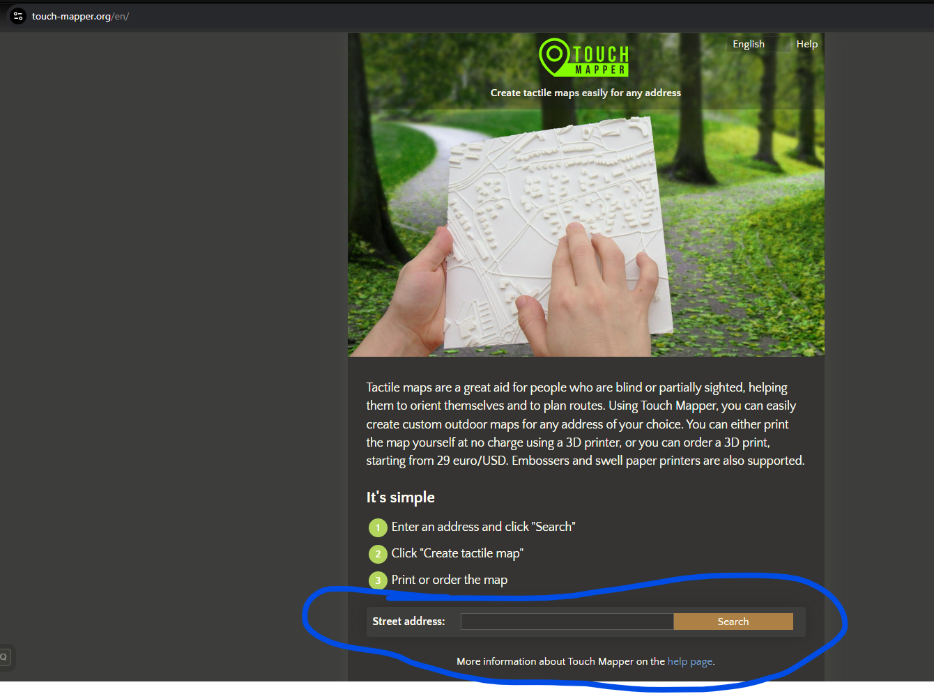
In the search bar, type in a location you're interested in. If you haven't already, also be sure to ask your user what locations they particularly had in mind. Touch Mapper can get very, very granular, so if your user had a specific place in mind, be sure to ask ahead of time!
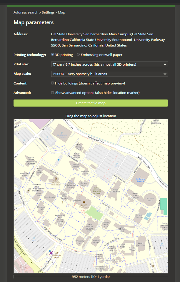
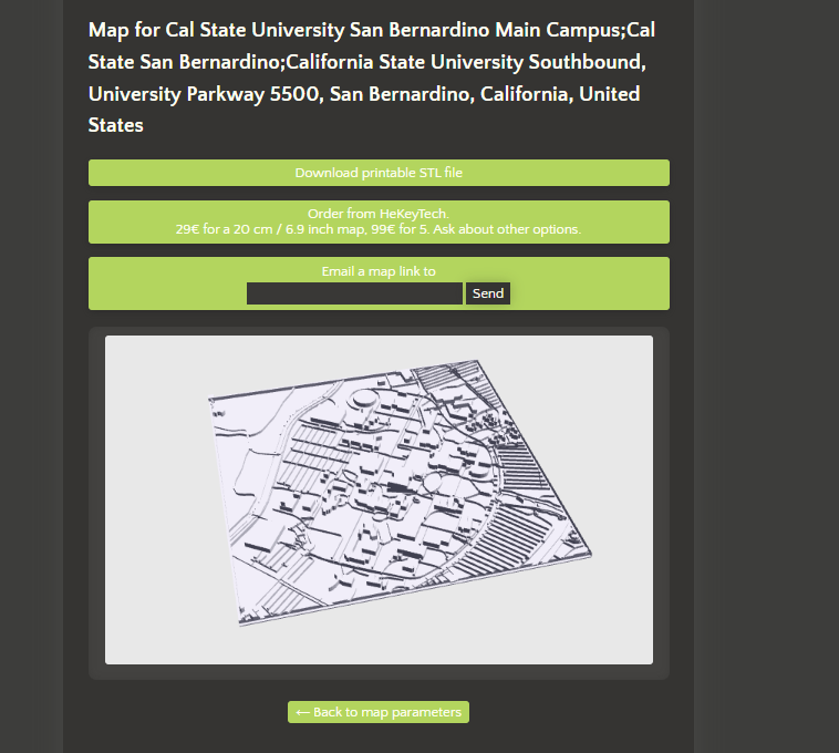
Once you've got the location centered, click on the "Create Tactile Map" button. This will start the process of creating an STL model that we can then edit in Blender. Fun fact, my office is in the pointy in of "The Wedge."
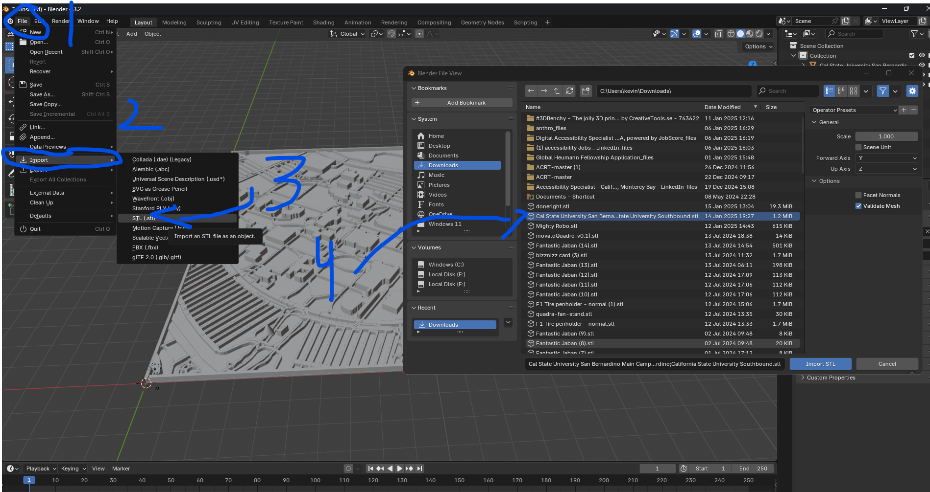
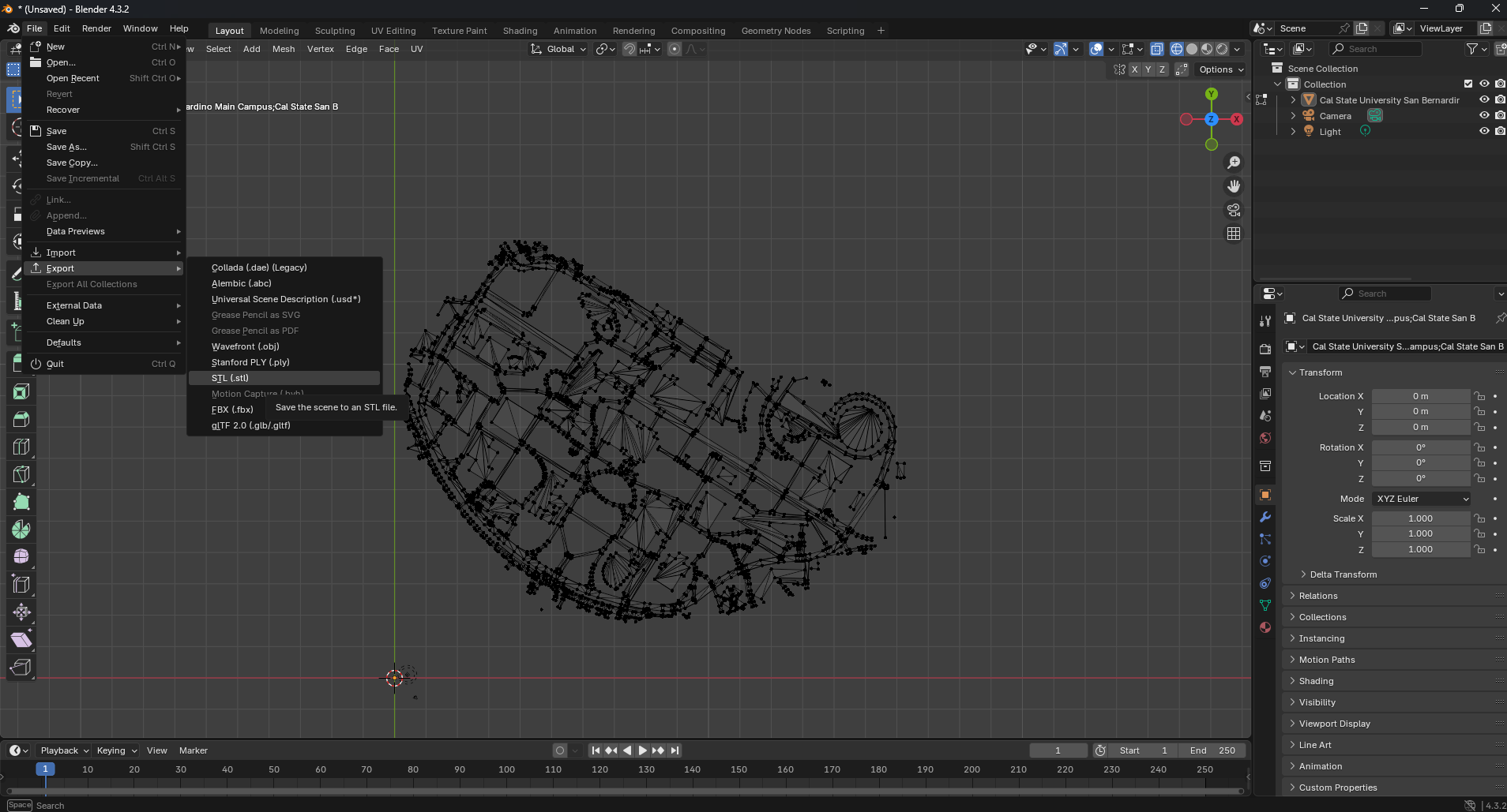
Now, open up blender (it's free!), and import the STL into the program. Blender is really, REALLY confusing the first time you open it (and also the hundredth time), but we will only be using a few things in it for now. First, open the file menu, come down to the import option, select STL, and then look for the STL file you made in the previous step.
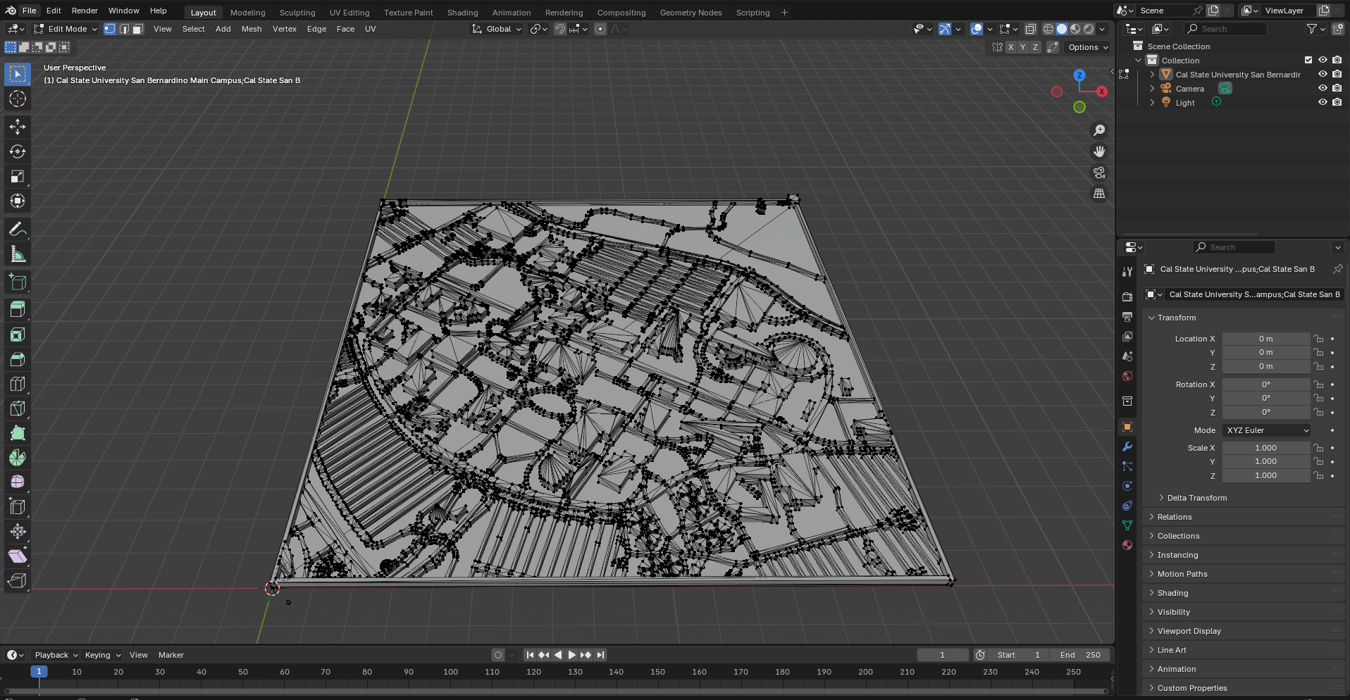
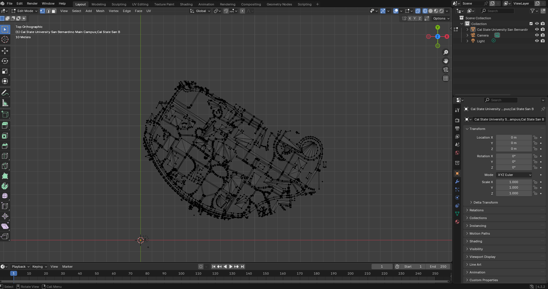
Ok, this next part is the most technical part. It's a bit hard to explain, so I have this technical part from the video linked here. Basically, you want to remove the unecessary parts of the model. This is also where you need to talk to your user. Do they want the whole campus, including the parking lots? Or do they just want the buildings and path ways on campus? For my user they JUST wanted the main part of the campus. So, we need to edit this. So first, delete the default cube, then select the STL model you imported. From there, hit tab, which will take take you into "Edit Mode" for blender. The once previously solid grey model will now have a bunch of little dots over it. These are the "vertices" for the model, and what you can individually edit on the model. There's a LOT you can do with these, but for right now, we are going to be using the lasso tool to select the parts of the model we want to delete.
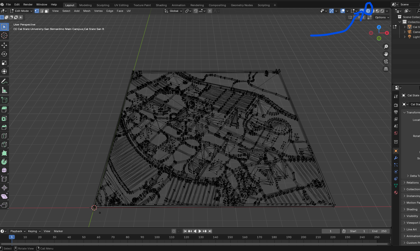
Now in edit mode, click on the far left "globe" icon. This will change the view of the model to "wireframe" mode. This will make it easier to see the individual vertices of the model, and also make it easier to perform the editing we need to do.
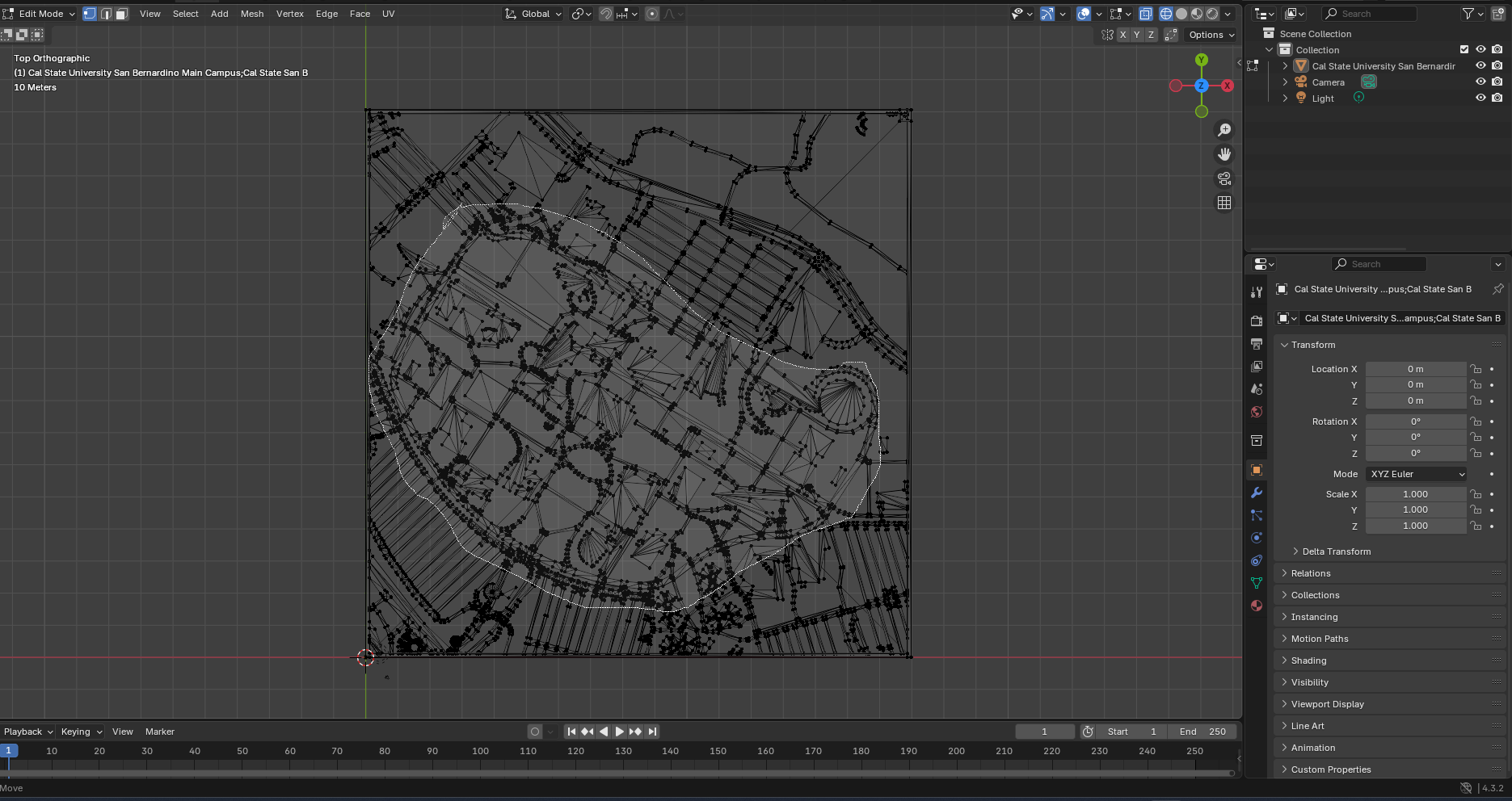
Now, we want to change our view to a top down mode to more easily select the parts of the model we want to delete. To do this, press the "`" key, which is the key to the left of the "1" key on your keyboard. Then select the "top" view.

Now we get to use the lasso tool! Press Ctrl, and hold down right click. Use this to select the area of the model you want to keep. For me, I want to keep just the center area of the campus. No parking lots for me.
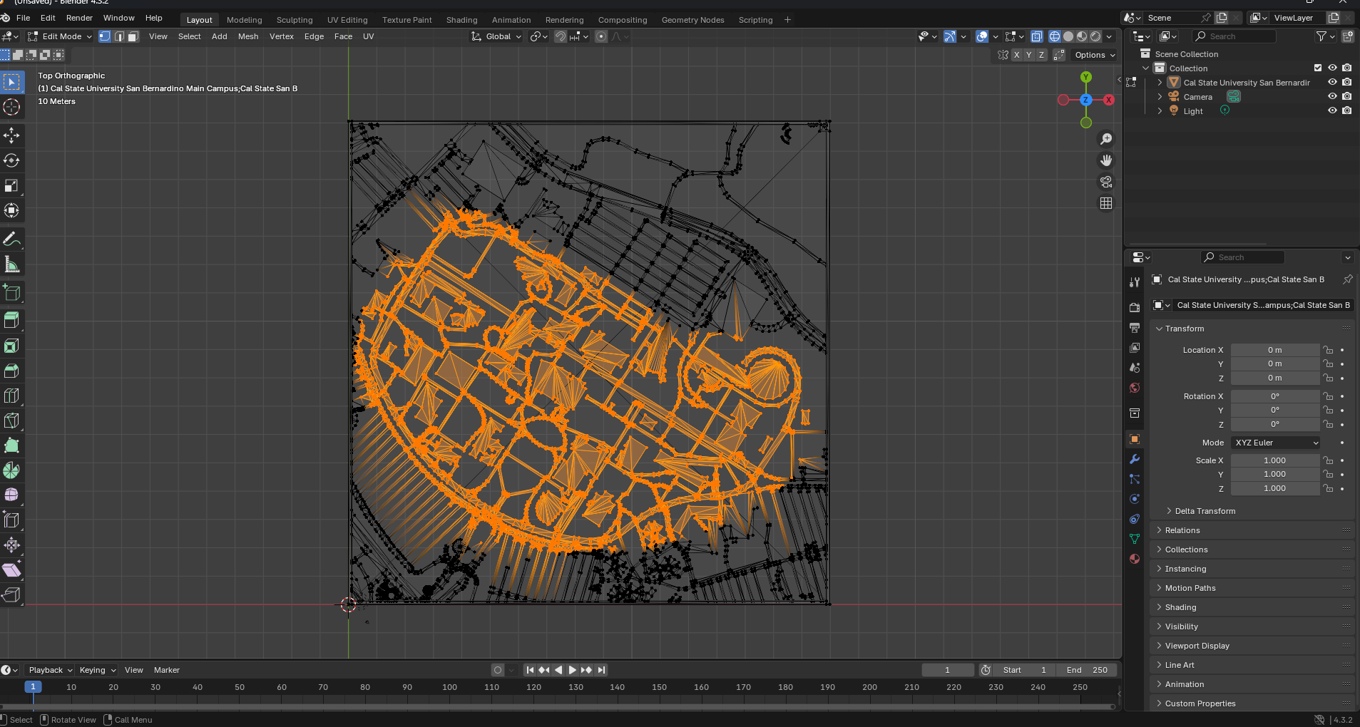
Now, the magic part. Press Ctrl + I to invert the selection, then press the delete button, then select the vertices.
Now we have the area of the campus we want to keep! Save, and then export this as an STL file. After this, we can close Blender.
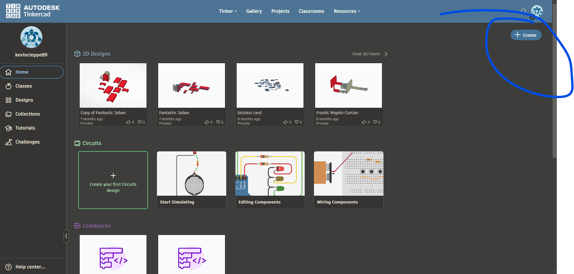
Next, open of your favorite browser, and head to Tinkercad.com.This may be the actually best service I've ever come across by the way. It's a 100% online 3D modeling platform with either unlimited storage, or really really high storage. Seriously, I have like 150+ projects in it and I've yet to hit a data cap. AND the platform is very intuitive, but powerful. Tinkercad, if you ever read this, you guys seriously need to let me give you money somehow. So go to Tinkercad.com, create an account, and click the create button, and then click "3D Design".
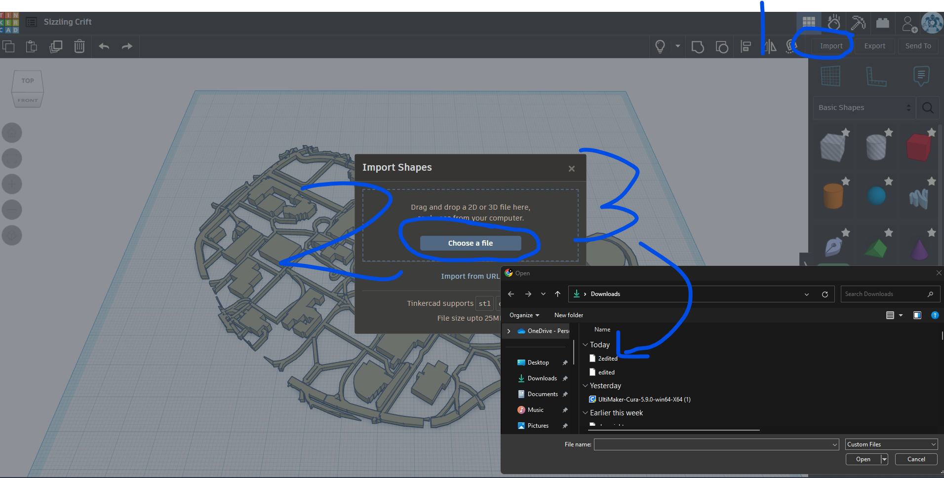
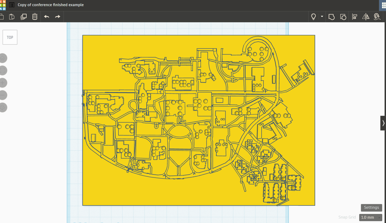
Next, once you're in the Tinkercad workspace, click the import button, and look for the STL file you just made in Blender.
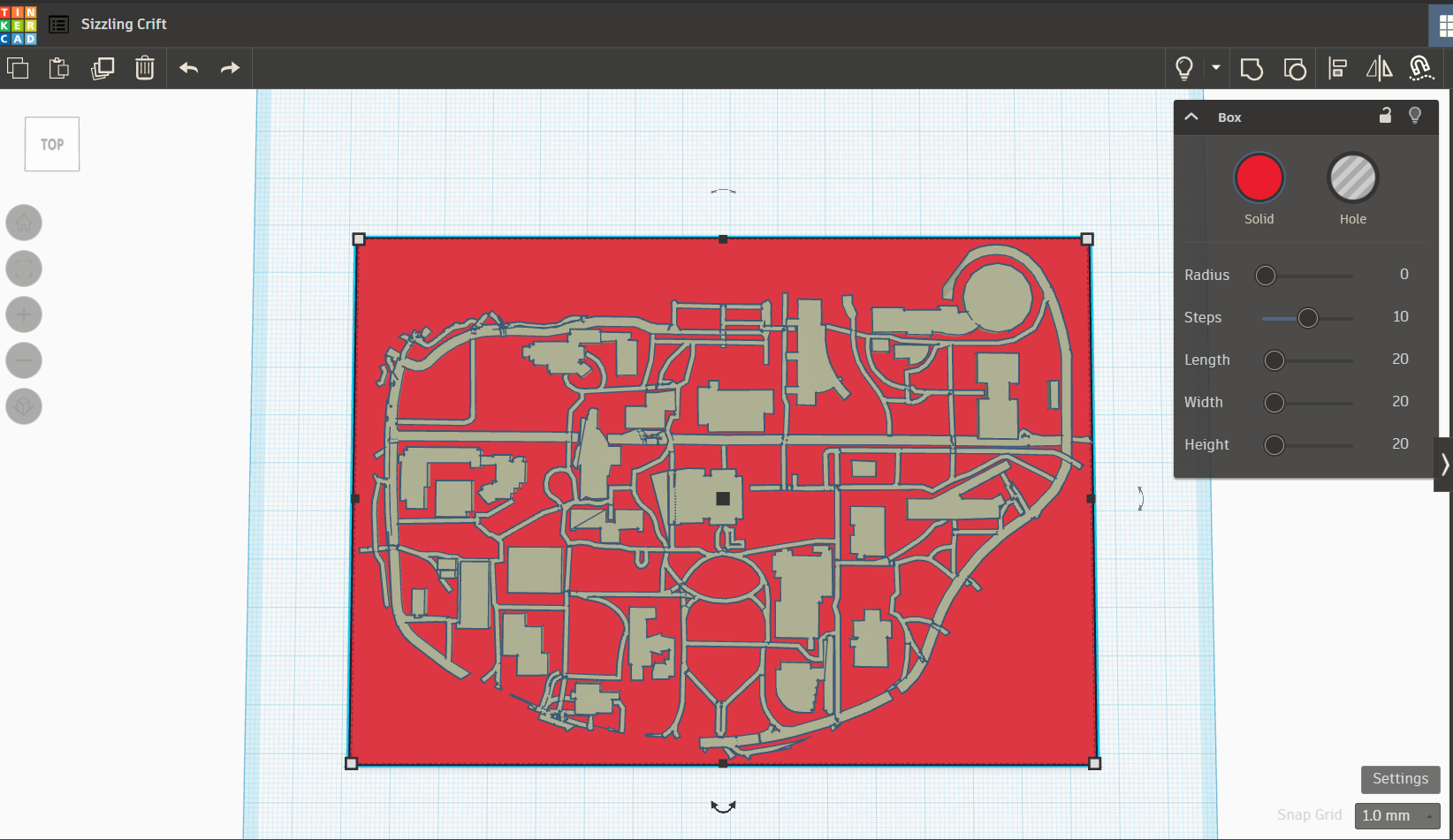
We can finally do some editing. First, we need to give the map a base plate, otherwise if we printed this out as is it would fall apart. Go to the shape section, drag a box onto the workspace, and "squish" it down until it matches the shape of the map. I have the part of the video that shows how to do this linked here.
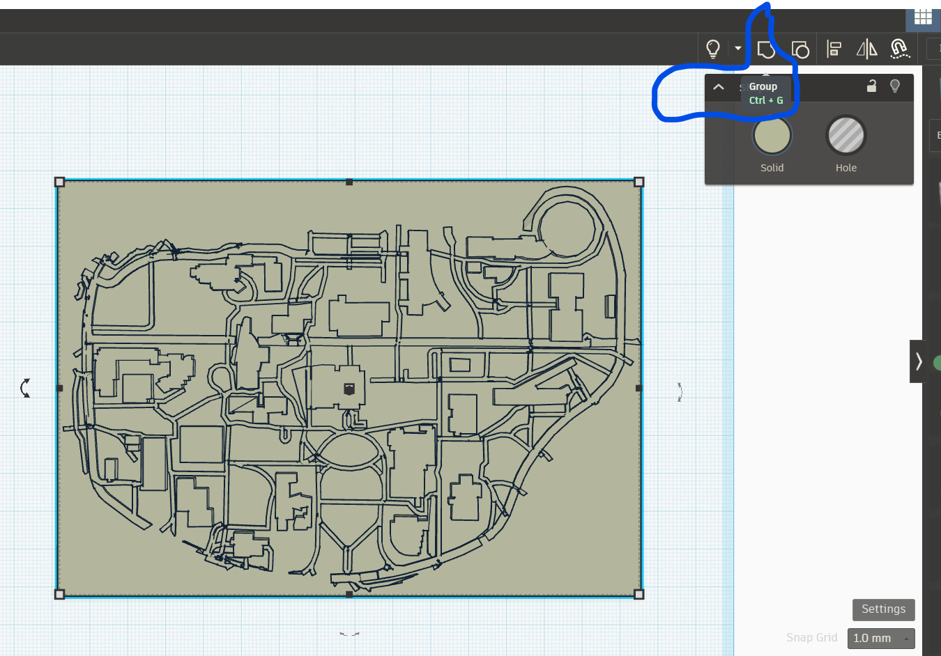
Now we need to combine the two shapes; the map and the plate we just made. To do this, left click, and drag a box over the two shapes (you can also press Ctrl + A to select all the shapes). Once you have these selected, select the "group" button in the top ribbon. This will combine the selected shapes into a single shape.
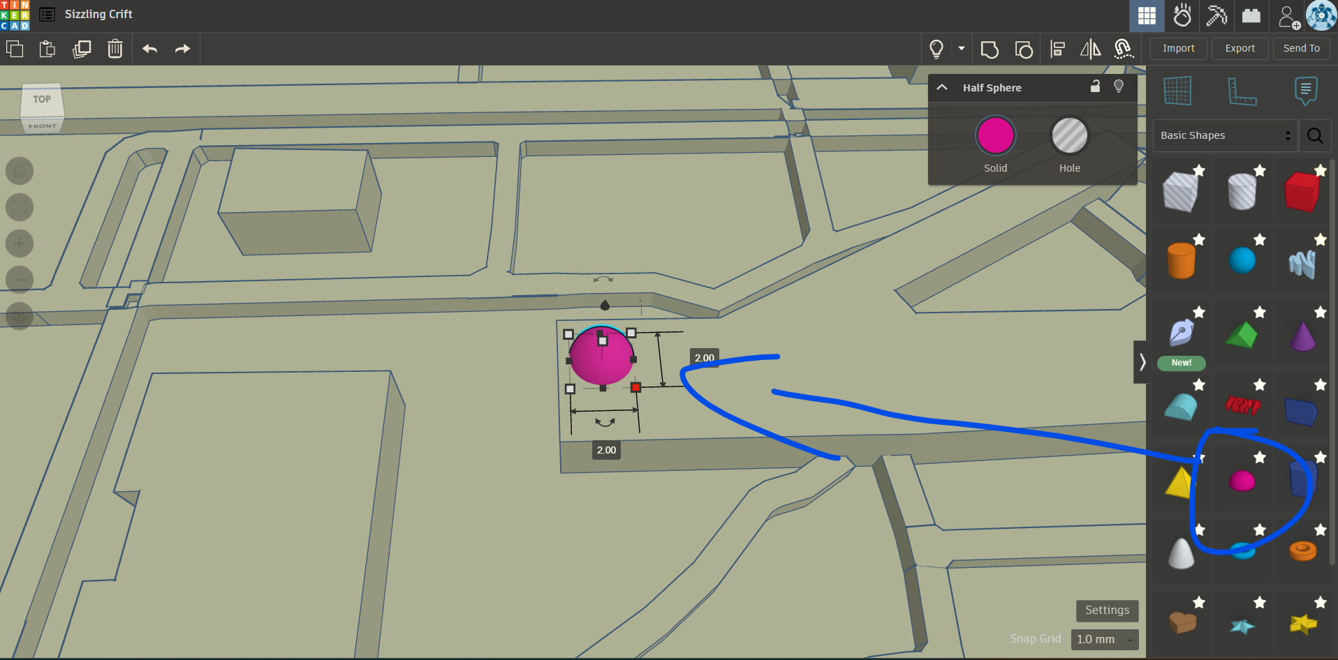
Now is the tedious but still kind of fun part of adding the braille to the buildings. For our campus, we used the building acronyms for the braille (for example, Jack Brown becomes JB). Go to the shape section, and drag a half circle on to one of the buldings, and size it so it will fit onto the top of the building you are making the braille for. Make sure the size of the half circle is an even number for width and length. You will see why in a moment.
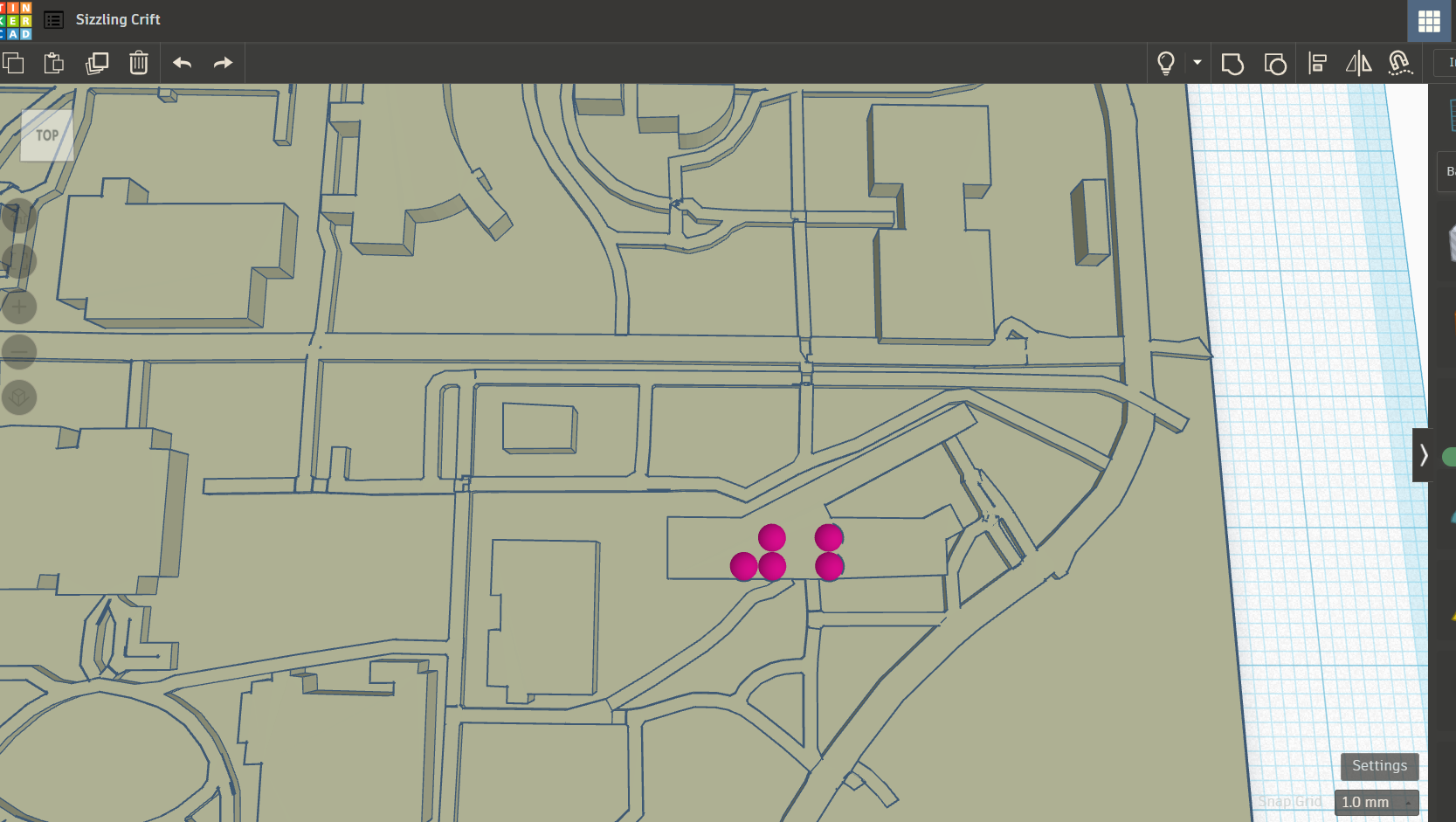
Now that we have the first bit of braille, we need to replicate to spell out the acronym for the building. In the case of Jack Brown, we will be making "JB" with the half circle. Remember when we made the half circle 2 x 2 MM in length by width? We did that so we can copy and paste the braille, and have them align perfectly with one another. Copy and paste the semi circle, and use the arrow keys to position the objects so they line up correctly, and spell out the acronym for the building.
Ok, now the somewhat tedious part. We need to replicate this but for all the buildings. Like I said at the beginning, it's a good idea to ask your user ahead of time what area they want. Not only will it narrow down your work, you won't have to replicate this step for every building. Rather than document this for EVERY building, I'm going to jump a bit ahead so we can get to the best part, the actual printing of the map! Note: because the actual size of some of the buildings will make it difficult to rest the braille on top, you may end up with some braille that is a bit off the building. Most printers now a days can handle "overhangs" like this very well. So as long as it's not completely off the building, you should be fine.
Finally, we get to print this thing! Be sure to group all the objects together as one singular object, and then then download the STL of the map. Once this is downloaded, open the STL in your favorite slicing software. In this case, we will be using Cura.
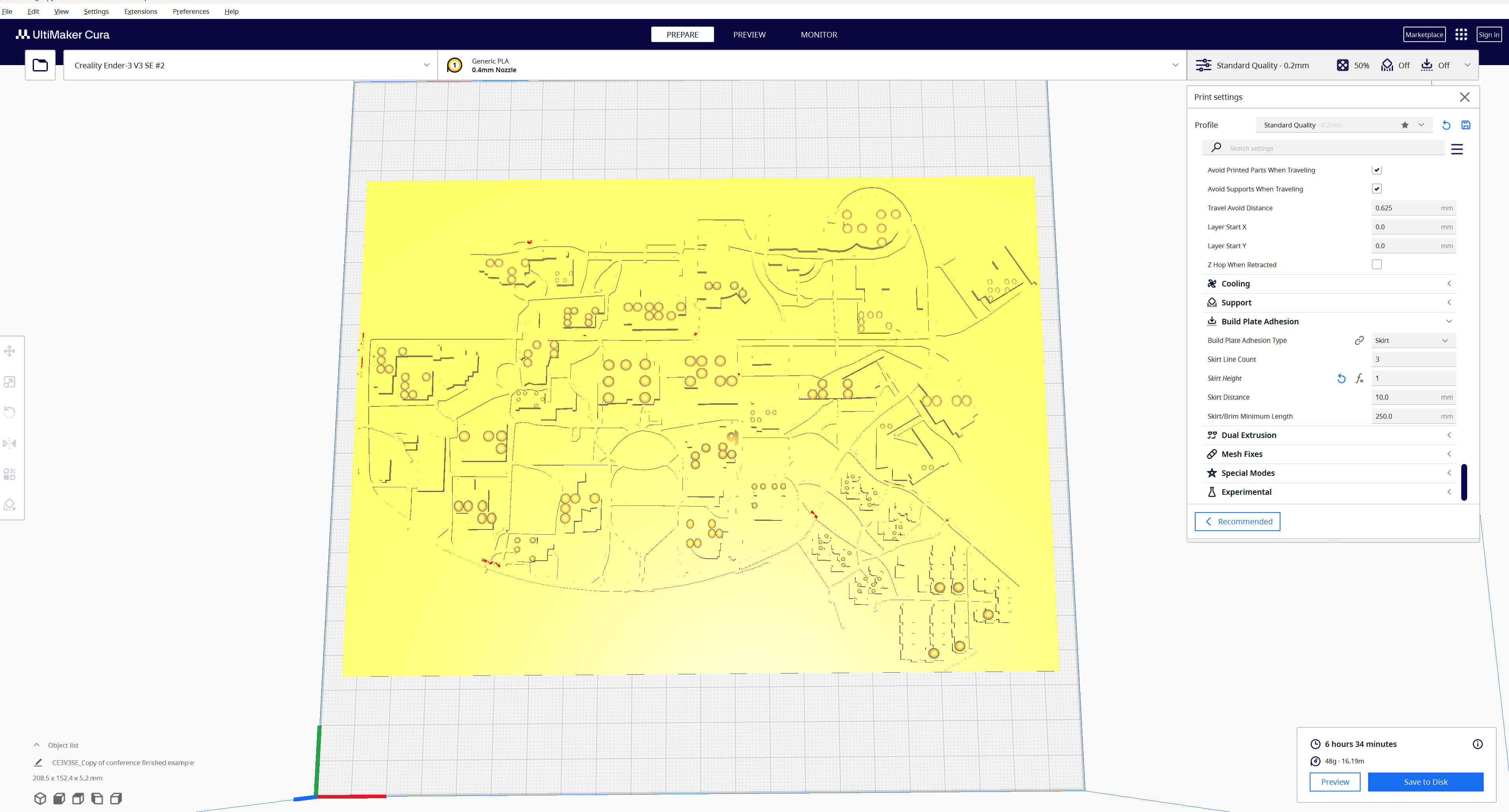
Cura is a "slicing" program. It takes the 3D model you have and "slices" it into layers. Basically, it takes a 3D model and gives your printer a step by step guide on how to make this once digital assest into a real physical object. I also compare it to like the artist rendering of a building versus the actual blueprint for how the building will actually be made. Most of the settings can left as default, but I do like to change the speed (I am using a Ender 3 V3 SE) down to 135 (the default speed of 180 is way to fast!), the infill to 50%, and the layer height to 0.16mm to make sure the braille gets enough definition. Adjust your settings as needed, and I also like to put a little bit of gluestick on the plate to make sure the flat surface of the print properly adheres to the plate. Slice it, put the file on an SD card (or upload it to Octoprint if you're fancy like that) and hit print!
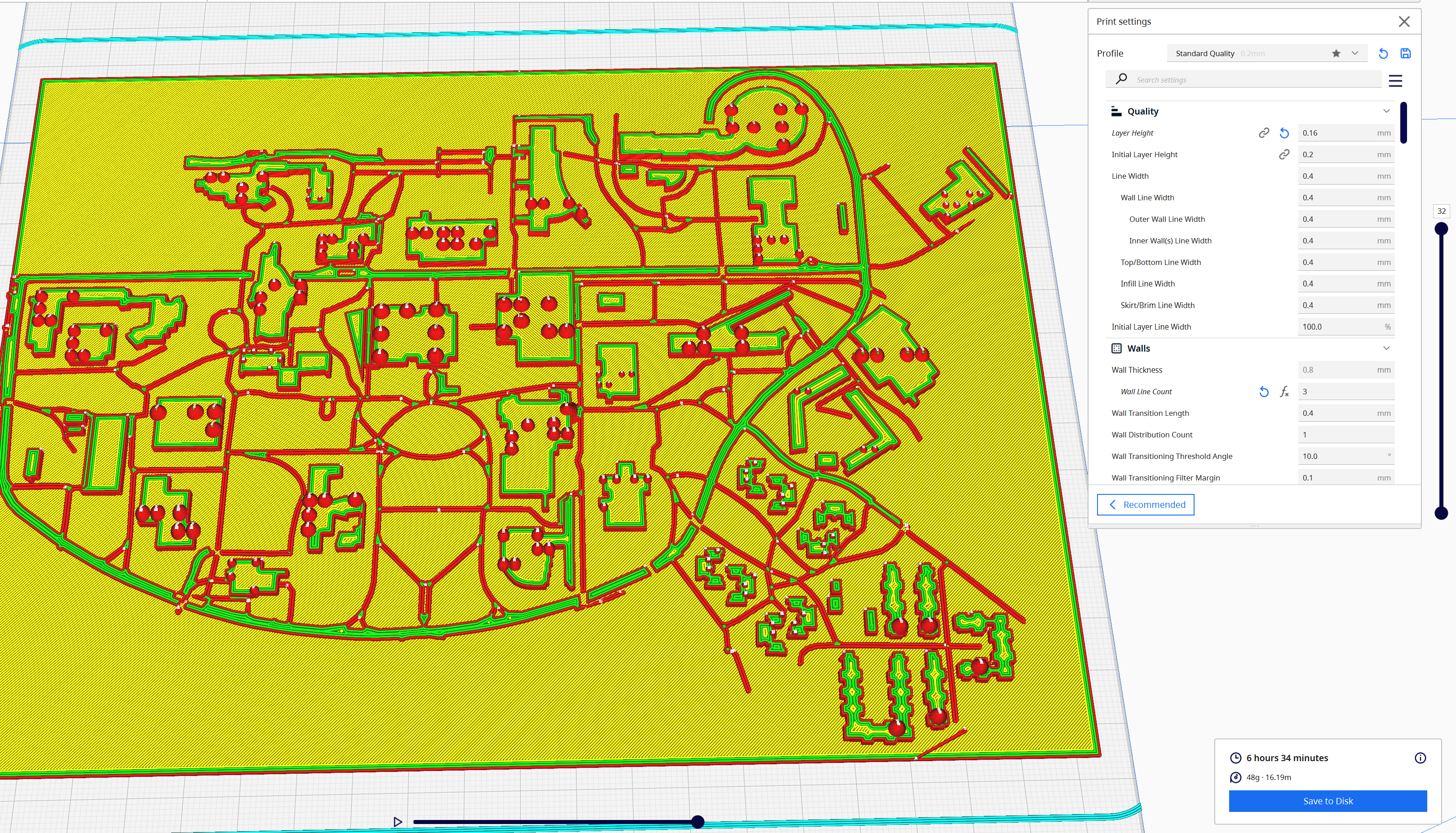
6ish hours later (or longer depending on your settings), you have your tactile map ready to go! Now you have to do arguably the most important steo of this whole process: get feedback from your user! The map might be great for you, but what does your user think? Is the braille large enough? Are the pathways between the buildings clear? Do they want a different area? Now that you've gone through this whole process, you'll know wxactly what to change for the map to meet your user's need. For me, my user enjoyed the map, but then asked for a more specific one that was centered on the dorm area. Now that I've done this a few times, a customized map like this was easy to make. If you have any questions on this whole process, please reach out!
 (1).jpeg)